Case Studies
Snapshot
- Area: Stores → Dispatch handover
- Problem: Sundries dispatch errors (missing/incorrect boxes, partial loads) often found on site
- Constraint: High coordination load at dispatch across multiple concurrent trucks and multi-part jobs
- Intervention: Reorganised sundries staging — replaced shared racking with dedicated trolleys (one per truck)
- Cost: ~$1,400 (16 workshop trolleys)
- Outcome: ~75% reduction in sundries-related rework (based on daily reports / operational recollection)
Executive summary
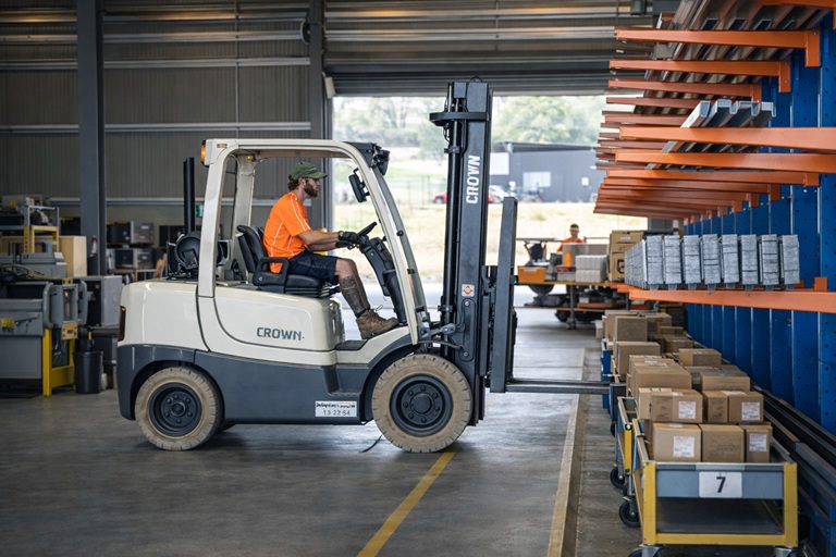
A Steel manufacturer was experiencing recurring sundries dispatch errors that created reworks, follow-up deliveries, overtime, and customer disruption. Errors had become “normal” and were handled reactively. A low-cost physical workflow change removed the main failure mode: instead of staging sundries on shared shelving to be found later, sundries were staged by truck using dedicated trolleys. The result was a decisive drop in rework without software, added headcount, or procedural enforcement. The change worked because it aligned how sundries were staged with how dispatch actually operates, removing reliance on memory and last-minute checks.
The situation
Roofing orders typically include large bundled streams (sheeting, gutters, flashings) plus sundries (sealants, brackets, fixings, accessories). Primary products flowed reliably because they were bundled and large. Sundries were the fragile link: small, multiple boxes, and easy to misplace,especially when several trucks were loaded in parallel.
The problem
- Boxes missed (e.g. only “1 of 2” was loaded)
- Boxes loaded onto the wrong truck
- Incomplete sundries discovered on site → follow-up deliveries & disruption
Critically, errors occurred at such frequency that a significant number, bypassed checks and were only identified on site, amplifying costs through time, distance, and disruption.
There was no single bad actor and no single “careless step”. The system was simply structured so that correctness relied on attention and memory at the worst possible moment:
under time pressure, at dispatch, with multiple trucks and jobs moving at once.
What was actually breaking
The original workflow:
- Sales → Stores: paperwork issued for job sundries
- Stores: sundries picked, boxed, labelled by hand
- Staging: boxes placed on shared shelving/racking with job stickers
- Dispatch: loaders later searched shelves, matched labels, and tried to ensure completeness per truck
This optimised picking convenience, not dispatch accuracy. With multiple component streams and parallel loading, completeness was hard to verify and “Box 2” could easily be left behind or staged incorrectly.
The intervention
Rather than adding checks or software, the physical storage medium changed from shared shelving to dedicated trolleys aligned to dispatch without compromising stores. This eliminated the primary source of error, by consolidating all job going onto a truck onto a single trolly.
- Purchased 16 workshop trolleys (one per truck)
- Assigned each trolley to a specific truck (numbered to match)
- Stores picked/packed sundries and left them on the trolley for that truck
- Dispatch loaded by moving the trolley to the truck and verifying completeness in one place
Additionally, the trolleys improved the entire workflow no longer needed to carry while collecting, and it removed searching for dispatch. The easiest way to work became the correct way, and checking all packages where present became a matter of checking, not searching.
Why it worked
- Removed ambiguity: one trolley mapped to one truck
- Reduced cognitive load: no searching and mental reconciliation of scattered boxes
- Earlier detection: missing items became visible at the truck/trolley level
- No enforcement needed: correct work aligned with the simplest workflow
Results
- ~75% reduction in sundries-related rework (approx. ~20/month to under ~5/month)
- Faster, calmer loading due to less searching and fewer last-minute corrections
- Fewer follow-up deliveries and associated overtime/admin interruption
- The change embedded without supervision or repeated intervention
Boundaries
- Improved sundries staging & dispatch accuracy only
- Did not change how sales created orders
- Did not eliminate errors in other product streams
- Did not remove the need for final dispatch verification
Key insight
Effective solutions must fit the real operating environment and the upstream and downstream processes around them. Changes that improve one step while adding friction elsewhere do not survive beyond enforcement.
In this case, the problem was well known but had become normalised. The solution worked because it made work easier for every role in the flow, removed reliance on vigilance at dispatch, and eliminated the need for ongoing management attention.
Notably, the change was driven from outside the stores and loading function. It succeeded not through authority or ownership, but through a clear understanding of how work actually moves through the organisation.
Snapshot
- Client Name: Milford Industries
- Industry: Steel fabrication — Auto Accessories
- Date: 2025
- Prepared by: White & Co. System Solutions
Executive summary
Consistent errors in the development process were causing projects to run late and issues to be fixed once products had been through the full development cycle and released to the floor.
Following the existing process with minor refinements resulted in approximately 75% error rate reduction and a 50% reduction in first production run time.
This reduced frustration on the floor and increased overall throughput due to a reduction in chasing up errors.
Client background
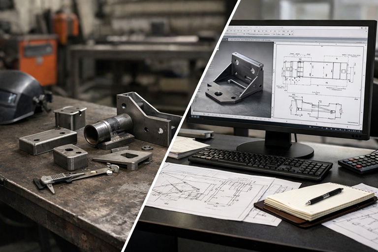
Milford was a leading manufacturer of steel towbars and cargo barriers, producing products for OEM vehicles with some aftermarket options. Most of the production is centred around fleet vehicles or HD recreational towing applications. Products are welded by hand with some high-volume towbars and tow hitches being welded robotically.
The business had approximately 60 employees between office, development, production, logistics and maintenance, with three consecutive shifts running through the week on the factory floor. It was not uncommon to have an overtime Saturday morning shift for catch-up.
The internal development team received requests and information made available by the OEM or gathered scan data from available vehicles. This was then used along with the in-house experience to design either a towbar, cargo barrier or both for the given vehicle. A typical project would go through a design review, prototyping, testing, tooling and manufacturing phase before being fully released for ongoing production of sales orders.
Design, testing, prototyping and tooling were completed by the development staff. When a preliminary design was ready, parts were made, welded and test fitted to the car. Any required changes were made to the design and an off-tool sample was made once the jig was complete. This was then fitted to the vehicle and then the project was released to the floor for the first production run.
The challenge
During the development cycle there were several errors that would be missed, resulting in the parts not being in spec when they were checked during the manufacturing phase where the first batch was made by the production operators on the production equipment. This resulted in rushed fixes and concessions to be made resulting in finished goods not meeting the spec of the design as provided by development, but still being approved fit for function in the vehicle.
While the development team was completing the design, creating machine programs and confirming that the parts fit in the vehicle they were not following a consistent process. Machine settings were not documented with achieved tolerances recorded. Some parts were manually manipulated after they had come off the machine to make them fit. Dimensions were sometimes taken from the model, drawings modified without record or additional views and dimensions put on a “draft/working” drawing when they were not available on the official part drawing. It was not uncommon that drawings would be updated without the revision being updated to, or the update made noted on the drawing revision block.
Our approach
Thomas Hollitt, one of our directors at White & Co. Systems, was specifically brought in to work closely with the development team to address the issues that were falling through the cracks, rather than just highlighting the items that had been missed at the end of the process during the first production run. Thomas was integrated into the development cycle to assist with design for manufacture and ensuring that prototypes were manufactured within spec with documented results so changes could be tracked.
Existing processes were already in place. Upon review there were not many updates required other than the need to follow the existing process.
Key updates included:
- Recording machine program and part dimensions during prototyping
- Drawing control
- QA check of parts used in fitment checks for formal records
- Lessons learnt follow up
Recording was introduced to document all machine settings and the dimension of the parts recorded with the equipment available in production (the same equipment used to confirm if parts are in spec by operators during their first off). Nothing fancy, just a handwritten record on the back of the drawings showing the machine setting used to achieve a specific feature, with the dimensions of the batch of parts that were made using that machine setting. This allowed for consistency and achievable tolerances to be tracked. None of the equipment had changed prior to Thomas joining so all data collected was indicative of the results that the development team had been making previously.
Drawings control was the next major improvement. This was largely using the pre-existing workflows. However with the drawings going to someone outside of the core development drafting team, revision control became more important as drawings couldn’t change after parts had been requested.
Drawings were the main source of information used by the production team to manufacture parts. This resulted in a process of unifying dimensional approaches to align with the machine settings to be used (e.g. dimensioning and tolerancing backstop and angles on drawings as these are the only features that can be controlled on the floor; all other dimensions are driven from these). This simplification reduced the time spent on the floor trying to measure and tweak programs to match the drawing.
Where possible the machine settings used during the prototyping phase were recorded in a machine settings block in the corner of the drawing. This was particularly relevant for some machines that required an override of the existing program to make minor adjustments on the day to ensure parts were in spec. It also provided a historical baseline of what to work from if a part needed to be dialled in again in future.
Drawing revision control had typically been lax as only one person was working on a design across the development lifecycle. With the addition of Thomas into the process to look after prototyping this could no longer be the case. The drawings were marked as compliant to AS1100 requiring the need for author, revision, date and change since last revision to be accurate on each revision of the drawing. In instances where more than one drawing was printed at the same revision the development team was informed of the discrepancy.
For explicit formal record keeping, dimensional QA checks were completed once prototype parts, tooling and off-tool samples had been completed and measured as in spec on the floor. This allowed for a record to be kept of the parts so that should changes be identified during fitment there was a record of the dimensions they were working from. Additionally, 3D scanning was typically used to gather information of the vehicle for the design to fit within. This was available to use for making a digital record of the parts and their geometry for reference should required changes be identified.
Lastly, learnings from current projects needed to be discussed so that knowledge could be shared throughout the team. Documenting this can provide a useful reference of previously successful solutions that allow knowledge to be transferred to new team members. Closing the loop at the end of a project allows knowledge to be retained and transferred to reduce the incidence of similar problems causing issues in the future.
The solution
The largest change to the process was confirming that checks were completed and records kept throughout. This allowed for issues to be caught, identified and rectified before moving onto the next step. For example, if a part such as a strap was producing parts in a range that spanned below spec, in spec and above spec for a single machine setting then the tolerance provided was smaller than achievable.
Through the process of record keeping during prototype parts it became clear that this had been ongoing for years. As the parts are flexible up to 50mm in finished height without excess force the finished goods would still fit the vehicle with no issues, as confirmed by zero customer complaints about straps fitting vehicles over the last 20 years.
Simplifying the drawing dimensions and information, by including machine program blocks and dimensioning the features that can be controlled at the machine (e.g. backstop and angle) reduced the mental load required on the floor. If part is 1mm over the nominal dimension adjust machine by 1mm, rather than needing to calculate the dimension across a combination of multiple features.
Specifically, for straps this information informed the team that tolerancing the angle to ±2mm (which was achievable) would allow parts to remain in spec rather than tolerancing the height to ±2mm, which would begin to fall out of spec if the bent length was more than 50mm. It was not uncommon to have bent lengths upwards of 150mm.
Specific QA dimensional checks allowed for clarity of fitment parts. This provided clear records of what was achieved and the baseline of nominal for the off-tool sample. Including a 3D scan of the parts allowed for fitment issues to be checked such as how much clearance was still available between connecting parts and vehicle trims.
Finally, the biggest improvement came from completing checks in full. When checks at each stage gate were completed in full (e.g. prototype parts are in spec for the batch), then the likelihood of future issues arriving were minimal. Where checks were done from memory it was likely that these items would fall through the cracks and cause bigger delays further down the line.
As these had not historically been treated as a critical step in the process support was required from the management team to hold their employees accountable, ensuring that records were kept and checks completed in full rather than just ticking the box and “she’ll be right”. The time savings through the business more than make up for some additional front end, particularly when support is available for the first project cycle so that the benefits can be realised. Without this support it is not uncommon to see the benefits realised erode over time.
Lessons learnt close out at the end of the project discussing what went well, areas of improvement and providing a forum to discuss how the approach can be modified in future. Without the loop being closed at the end of a project the knowledge tends to fade to history over time and leaves with individuals as they change roles.
Results & benefits
Significant reduction of errors in production which can be seen in the graph below. Error reporting consistency was increased with a reduction of up to 75% in error rates across a rolling average of 4 quarters. Previous dips in error rates coincide with staff changeovers and no errors being documented during that period.
This resulted in significantly less time spent chasing up errors, typically during incredibly time critical deadlines when the development team has already moved onto other projects.
One of the key benefits that is difficult to convey in graphs is the increase in morale related to completing the first production runs. During this time lead times for first production runs were reduced from 4 weeks to consistently being successfully completed in under 2 weeks. Production would end up making parts faster than they could be checked through QA when they were able to make from the drawings without running into issues such as missing information or incorrectly programmed machines.
Key learnings / next steps
- Following a structured process can lead to significant reductions in errors requiring follow up throughout the development process.
- Following a consistent process and completing checks along the way can significantly reduce the required workload and error rates.
- Minor modifications to drawing layout increased clarity on the floor and ensured that dimensions could be checked accurately with equipment available.
- Lessons learnt create a culture of steady improvement within the business — celebrating wins and identifying areas of improvement for future similar challenges.
- The human element requires team members to follow established procedures. Being too busy is what causes mistakes to happen. Following the process, while it may take some time, will result in a lower total time investment across the business to complete the project.
Contact information
- White & Co. System Solutions
- Thomas Hollitt, Director & Lead Consultant
- THollitt@WhiteCoSystems.com.au
- whitecosystems.com.au
- +61 413 523 012

Snapshot
- Client Name: Revolution Roofing
- Industry: Manufacturing
- Date: 2017
- Prepared by: White & Co. System Solutions
Executive summary
A new ERP implementation introduced a significant amount of processing required to complete the scheduling process to release production orders to the floor and record material used for finished parts.
Streamlining the process reduced the load by five employees, who were released back to their normal duties.
Client background
Revolution Roofing is a steel roofing manufacturer, producing products through roll forming, bending and a number of custom processes. The business supplies products on a next-day turnaround, typically with less than 24 hours required to manufacture most products.
The challenge
Following the ERP implementation, the number of people required to process production orders to the floor increased to eight. Employees were pulled from other activities to manage the bottleneck of orders moving through the system.
A department that had previously been run by two people now required eight, and individual orders were taking up to seven to eight minutes to process.
Our approach
The approach focused on identifying the movements required to complete all tasks, including the number of different system locations that needed to be accessed.
The existing process required multiple screens to be opened and closed, frequent mouse use, and manual selection of input boxes for each action taken. These steps were analysed to identify unnecessary actions and sources of delay.
The solution
The system fields were reprogrammed so that a production order could be processed without hands leaving the keyboard, using the minimal number of input screens required to complete the task.
Results & benefits
Cycle times were reduced to approximately 15–20 seconds per order.
The department was reduced to three people, with additional scheduling duties absorbed into the role. This resulted in a net decrease of five employees for the department, who returned to their other duties.
Key learnings / next steps
- Reduce the number of steps required and actions needed when introducing new processes into the business.
- Run trials on new processes prior to implementation to identify potential bottlenecks.
Additional context
Streamlining the process of releasing production orders to the floor and recording material used to manufacture parts was critical immediately following the ERP launch. The initial implementation caused major roadblocks, with the scheduling department requiring eight staff pulled from other areas to keep up with demand.
Removing excess actions, simplifying the user interface, and providing training on how to process common errors and discrepancies reduced cycle times from over five minutes to under 30 seconds.
Key activities:
- Condensed timelines allowing excess employees to return to existing roles
- Streamlined scheduling process
- Training to resolve common errors and discrepancies
- User interface simplification
Contact information
- White & Co. System Solutions
- Thomas Hollitt, Director & Lead Consultant
- THollitt@WhiteCoSystems.com.au
- whitecosystems.com.au
- +61 413 523 012
Snapshot
- Client Name: SA HV electrical distributer
- Industry: Electrical distribution
- Date: 2021
- Prepared by: White & Co. System Solutions
Executive summary
The client identified a need for consistent instruction and operations for locking out HV disconnectors within their network. Equipment was operated infrequently, often requiring operators to spent time on site refamiliarizing themselves with varying equipment that had been acquired over many years.
A consistent package of consolidated illustrated steps was created for every type of disconnector in the network. With the client supplying a new consistent lockout point for each piece of equipment.
Client background
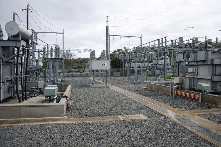
ElectraNet operate and maintain the high voltage (HV) electrical distribution network in south Australia. This equipment has been acquired over a number of years and is now at various stages within their own lifecycles.
The challenge
There are approximately 50 different types of HV disconnectors in substations across south Australia. Due to the large variety of different disconnectors and the length of time they have been acquired over there is a large variety of actions required to actuate and lock out each different type of HV disconnector.
The client identified a want to consolidate the action to actuate and lockout the HV disconnectors.
Maintenance has been conducted differently at different times in the lifecycle of the equipment. Most equipment gets serviced once a year with each piece of equipment needed to be disconnected from the grid while the works are underway.
Actuating the HV disconnectors needed to be carefully planed such that the removal of the disconnector from the grid for a period didn’t cause any instability. Operators needed to be onsite with inductions completed for every attending person. Available windows were often short with locations limited to see each type of HV disconnector. Often resulting in travel required to view one of the few available in the network.
Our approach
A standardised workflow and layout were proposed. With each specific type of disconnector covered in a consistent yet individualised work instruction. Where multiple makes and models had the same operation they were combined into a single work instruction.
The client had begun work on a standardised external lockout mechanism, with clear visual indicators visible from across the substation that the equipment was locked out. This formed a key part of consolidating the lockout out process with equipment having a consistent process and visual indicators for the mechanical lockout of equipment.
Working closely with the network scheduling team to book site visits often a month in advance. Flexibility was key to ensure that this work had minimal impact on client operations throughout this process. Most of the instructions could be written in the office from OEM operator manuals, drawing and maintenance pictures available digitally. All instructions were written using the available information with required pictures planed out for each required section of the instructions. Requiring only the drafted actions to be validated on site with operators and pictures taken of the actual equipment in the different configurations, such as open and closed.
The solution
Providing a consistent work instruction with clear steps and pictures showing how each HV disconnector operates. Instructions were kept consistent and with the physical external lockouts supplied by the client all HV disconnectors operated in a similar manner with clear visual indicators when the equipment was locked out.
A standardised workflow and layout was proposed. With each specific type of disconnector covered in a consistent yet individualised work instruction. Where multiple makes and models had the same operation they were combined into a single work instruction.
Results & benefits
Training on operating HV disconnectors was simplified with a common handbook with standardised instructions across all disconnectors that clearly and visually walked through how each disconnector was operated. Each instruction was linked to the piece of equipment in SAP so that time didn’t need to be wasted looking for the correct instruction arriving at site.
Key learnings / next steps
Simply consolidated instructions stored in easily accessed locations reduced confusion when operating equipment that maintainers actuated infrequently.
Contact information
- White & Co. System Solutions
- Thomas Hollitt, Director & Lead Consultant
- THollitt@WhiteCoSystems.com.au
- whitecosystems.com.au
- +61 413 523 012